Becoming an Engineer
In the first session of an engineering class I took during my engineering program, a fellow student asked our professor, “why aren’t you teaching us the code?” The professor’s reply was “I’m teaching you engineering.” This question posed to a professor came up again in my upper engineering class and we got the same answer: “I’m teaching you engineering.” This exchange always puzzled me until I started practicing engineering. I discovered that what he implying was about solving problems that had consequences for public safety.
In this discussion of “What is the Solution?” let’s begin by considering some historical perspectives. The concept of “An Engineer’s Coffee Break” is based on an open dialogue about an observation that results in a solution. This can be traced back to 17th Century England’s early coffee house traditions. An example of this environment is a notable meeting between three Royal Society members, Christopher Wren, Robert Hooke and Edmond Halley, and their discussion regarding an observation of celestial motion(s) as a function of the “inverse square law,” but needed a proof (The 4D Solution). The Royal Society’s motto is “Nullius in Verba” (Latin for “take nobody’s word for it”). The solution was Isaac Newton’s “Philosophiae Naturalis Principia Mathematic,” published July 5, 1686.
OK, let’s begin.
Let it Walk
The 4D Solution – “Let it Walk” is primarily about a publication I wrote with a colleague titled “Seismic Scaffolding Concerns? Let it Walk,” (Nuclear Plant Journal, May-June 1990, ISSN: 0892-2055) which in a small part was in response to the Three Mile Island accident on March 28, 1979 and the Chernobyl accident on April 26, 1986, both of which changed the nuclear industry’s operations.
For example, during the 1980s, concerns were raised regarding the practice of using temporary work platforms such as scaffolding that were erected near “Safe Shutdown Equipment” in a nuclear power plant. The problem is that supporting these temporary scaffolding by securing against a seismic event, by attaching to either the containment building structure or adjacent components, could have these system’s design basis and/or operations, potentially resulting in a “Beyond Design Basis Accident.”
The 4D solution is about determining the relative response for a freestanding object(s) during an earthquake a colleague of mine had provided a video of an office during the Kobe earthquake in 1995. This video changed the Fort Calhoun Plant Committee’s perspective about “letting it (the scaffolding) walk.” I later used this video as a basis to communicate this concept. When presenting this information to the board, it was obvious that the perspective of letting temporary work platforms system slide back and forth was reasonable and therefore accepted by the committee. Matt gave me a new perspective of engineering. His communicating the information in this manner provides a perspective of what can be achieved by simple example.
Let’s continue.
The “Aha” Moment
The “aha” moment is when you discover the cause for an unexplained condition. In the practice of engineering we use the principles of mathematics, science, all available information, and common sense (common to). Mathematics and science are based on proven techniques that are relevant to specific assumptions. The availability of information such as current loading, support strength, type of material, variability of site conditions, etc. is not always available and assumptions are made based on your education, knowledge and experience. Common sense can be complicated, as it depends on how you communicate the issues to a broader audience. This can result in a discussion of what is “common to” the individuals’ knowledge and experience and what is important.
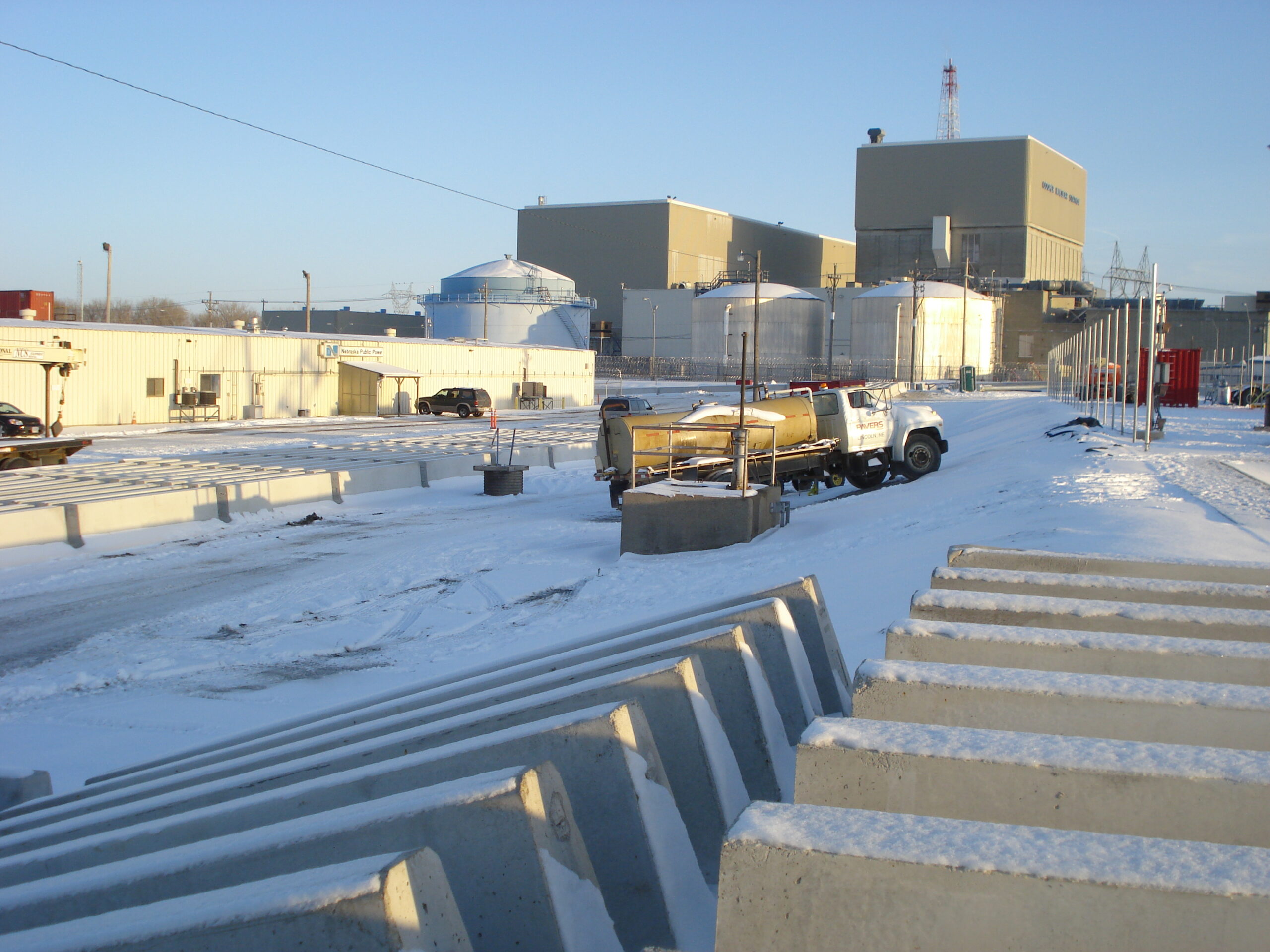
In my experience as a practicing engineer, an answer to a problem is not always immediately apparent. In March of 2008, a generator transport activity during an unusually rainy season resulted some road damage. This unexplained condition is based on a road segment with adequate drainage, loading capacity and additional surface stiffness from 1” plates. The haul route for this move of the generator started at the rewinding staging area concrete pad and surrounding yard area and roadway to the main road that was supported by 4” base and 2” surface coarse of crushed limestone gravel. The road from the staging yard to the main road was unspecified asphalt coarse. The road damage only occurred at the transition from yard to the asphalt road where the 1” plates were laid for additional load distribution. The main road is a standard asphalt pavement with 1-1/2” plant mixed BIT surface, coarse 1-1/2” mixed BIT binder and 6” aggregate base coarse and was the original haul route for the site excavation. The access road to the rewinding building was on 3” coarse gravel. Finally, the plant original site subgrade was removed, dewatered and replaced with highly compacted river sand.
Let’s continue.
Stater Large Project Task
The Innovation in Managing Material Aging (MMG) for the next generation of engineers requires a different perspective of the constraints and nature mapping elements for a “user-centered design.” This means the perceptible affordance has to be transparent to an uninformed user. The initial information will have to be basic, leading the user into next steps of understanding with clear guidance of the current information/state and hints to next available actions. In addition, there also needs to be a historical perspective of the design, construction and operational perspective of the information being provided. The information has to be clear, easy to understand, and offer a verifiable check of any solution presented.
Appling Technology used the original Seal Shell-2 program developed by the Atomic Energy Commission that improved on the Love-Kirchhoff hypotheses limitation relative to the accuracy of stresses, strains, deflections, and reactions in thick shell of revolution with axi-symmetric loading (temperature, pressure, circumferential forces and moments). The program’s methodology is based on an ingenious and well-developed algorithm for determining the stress distribution as proposed by the Love Kirchhoff hypothesis.
A Marmaduke Story
Inspector Slag looks up as Marmaduke the Radiation Protection Technician begins the entry briefing. “It is late in this refueling outage,” he says, then pauses and slowly sips his coffee, “and we need to inspect the Sand Pocket Drains, deep inside the Reactor Vessel Containment Building and Torus cavity…”
Okay, being an engineer is sometimes very much like “The Maltese Falcon” detective stories where Sam Spade investigated the scene, gathered evidence, researched the facts, solve the mystery and apprehend the culprit.
In 1980, the Nuclear Boiler Water Reactor industry discovered wall thinning of the drywell. A permeability coefficient of 0.84 in/min and represents a flow rate conservatively at 9.8 in3/min (0.3 gals/hr).
In the case a single Drywell sand pocket drain line is found to be obstructed, then the potential exists for a buildup of moisture in the immediate sand pocket area. However, because of the concentric continuity of the sand pocket design and as long as adjacent Drywell Sand Pocket Drain line(s) are functional, any significant moisture would be drained by these nearby lines, removing leakage water and precluding any potential impact the Drywell liner. As previously demonstrated, having four of the eight Drywell sand pocket drain lines functional was sufficient to preclude an environment that could lead to loss of material to these inaccessible areas of the drywell bio-shield liner.
The worst-case condition is when all lines are plugged and subsequently the air gap and sand pocket is full of pure water. This condition does not challenge the primary design function for stress distribution of the Drywell liner. However, this pure water environment condition for a non-alloyed material (ASTM SA 516) does result in an active corrosion mechanism and has the potential for material loss of about 25 mills/year, excluding any additional mechanisms.
When considering the industry experience, it would suggest that even under a worst-case general area material loss condition of about 25 mils (0.025 inches) assumed to occur over an operating cycle, there would be an insignificant challenge to the integrity of the Drywell liner shell, which has a nominal thickness of 1.5 inches.
Therefore, even if the worst-case rate of corrosion were assumed since the last inspection, the loss would be minimal.
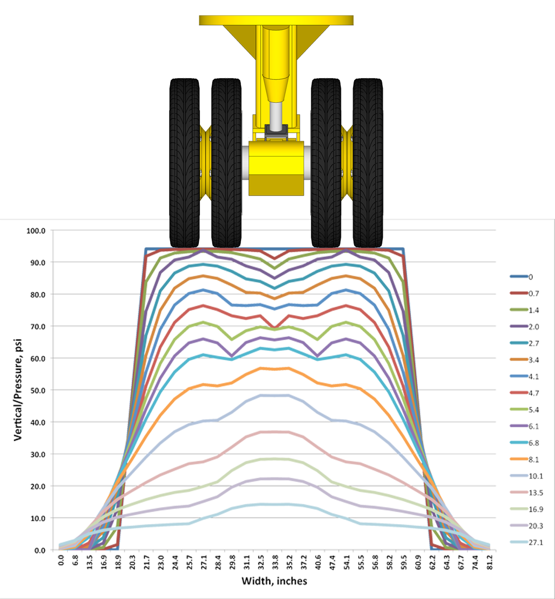
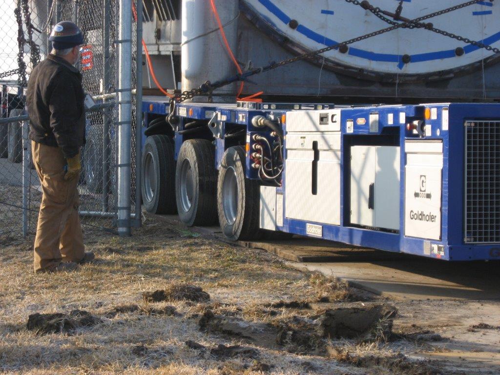
In August of 2014 I was asked to independently review another site’s generator and transformer project for their heavy load transport activity. Any heavy load transport review must start with determining the site’s geological relationship to the underground structure with a focus on structures, system and components using the Boussinesq method to determine the depth of significant influence (DOSI) that “The depth DS is a finite depth below which there are no significant strains in the soil mass due to the loads imposed at the surface.” (FHWA NHI-0The bottom surface layer is described by (Yoder and Witczak). However, a very important fact that should be clearly understood by the reader is even though stiffer material reduces the risk associate with a sub-grade mode of distress, such as shear, the presence of this stiff layer brings about an increase in the tensile stress magnitude at the bottom of this layer as well as a mark increase in the horizontal shear stresses. Thus, a subsequent design analysis is required to ensure that both the shearing resistance and the flexure resistance of this stiff layer are great enough to sustain these higher stress condition
The transport vehicle crew’s experience for a wet soil condition was to apply a steel plate to increase sub-soil stiffness. However, the unspecified asphalt road horizontal shear and flexure resistance was not adequate. In addition, the sub-grade crushed limestone gravel was capable of supporting the transport vehicle loading in wet asphalt road distress, a.k.a. the “Aha Moment.” The decision was based on only one engineering principle that was common to the crew’s experience that needed “The 4D Solution” to understand all loading conditions.
Another Perspective
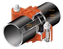
I was asked by a colleague to go to the plant and look at the floor of intake structure’s emergency power room. The problem was that a water line from the discharge area had been welded into the emergency power room. A specific issue was that you couldn’t get access to the other side of the wall to repair this line because it was always flooded. The standard fix for this scenario is to drill pilot holes around the side and then pump the water out of the room. I was able to find a device that I could use to clamp a new line to the end of the water line that isolated the power room from flooding – simple fix. Later, the plant was flooded completely except for this area; see fix below as defined by the ASME code.
Fatigue Monitoring Desktop Guide
Woods, K. June 24-28, 2012 (Conference Proceedings) “Fatigue Monitoring Desktop Guide,” ICAPP 2012, Nice, France.
This new perspective provides a different approach to cycle counting that incorporates all of the information about the material conditions. This approach goes beyond the consideration of a static analysis and includes a dynamic assessment of component health, which is required for operating plants. This health definition should consider fabrication, inspections, transient conditions and industry operating experience. In addition, this collection of information can be transparent to a broader audience that may not have a full understanding of the system design or the potential causes of early material degradation. This paper will present the key points that are needed for a successful fatigue monitoring desktop guide.
I. Introduction
What defines a successful fatigue monitoring desktop guide? This statement in essence provides a template of the primary elements for this discussion on the design philosophy for the development of a MMG (Managing Material Aging) program. The aspect of successful is really a consideration for “Affordances,” which is simply the quality of the program being used by an individual(s).
This discussion will begin with what constitutes a successful MMG program. In order to define these characteristics, it will be necessary to have a perspective of the individual(s) who will be utilizing this MMG program. This insight is rooted in the originators’ theme for the development of American Society Mechanical Engineering (ASME) Boiler and Pressure Vessel Code Section III Rules for Construction of Nuclear Vessels1 that considered the needs of users, manufacturers, and inspectors as well as good practices for owners.
The original perspective of applying “fatigue” by ASME code is a design approach for assuring material ductility. However, the current industry emphasis is to use this methodology and/or a modified version of the ASME code as a tool to determine time limiting aging analysis (TLAA). This discussion will present a perspective on how this method can be applied effectively.
The key to an effective TLAA is the availability of information that accurately presents the current material condition for future projection of component life. The challenges in this approach ar9G program should be to provide a means to acquire and input of legacy knowledge of past events from individual plant personnel. This discussion will present an approach in achieving this theme of affordance for a MMG program.
II. Successful MMG Program
To establish a successful MMG program we need to understand the term “affordance” coined by James J. Gibson2, which is perception drives action. This concept suggests that a particular environment as presented to the user achieves either a perceptible, hidden or false affordance. In the case of perceptible affordance the user achieves the correct action(s), and in hidden or false affordance results in mistakes or unintentional action(s) by the user. For example, it has been suggested that a contributing factor of Three Mile Island’s (TMI) accident was the plant operators’ false assessment of an actual system condition. A finding from the President’s Commission³ reads:
“However, operator confusion, which was evident during the accident, may have resulted in part from the control room layout and design or from equipment malfunctions which occurred.”
This event represents a hidden and/or false affordance as the operators’ false perception of the current state resulted in incorrect actions. This confusion was identified as related to the arrangement of emergency system controls, number of alarms (1500), indicator color lightness and/or valve position indicators, etc.
In order to achieve a correct perception, it is necessary know the MMG program user. This user can be considered the fourth-generation workforce for the nuclear industry. We consider the first-generation (Criticality) at the first-self sustained nuclear reaction to be the Chicago Pile-1 in 1942, by Enrico Femi and Leo Szilard who were 41 and 44 years old, respectively. This effort was based on Albert Einstein theory E=Mc2, who was 64 years old, and confirmed by Lise Meitner and Otto R. Frisch, who were 64 and 38 years old, respectively. The second-generation (Commercialization) starts with the first nuclear submarine, the USS Nautilus commissioned in 1954 and the Shippingport commercial power plant in 1957. Admiral Hyman G. Rickover, who was 54 years old, supervised design, construction, testing, training and operations for both power plants. The third-generation (Peak) began with the height and decline of commercial nuclear power, which can be marked with the TMI commercial reactor accident of 1979. The current projection is that most of the nuclear workforce will have reached age 50 years by the end 2010. This information provides some perspective of the growth of nuclear technology and development. The first generation was exceptionally fast paced, and the second generation was a period of steady growth, with both generations’ workforce interfacing with their senior counterparts to exchanging knowledge and experience. The third generation is relatively from a stagnant growth period and can be considered as a re-learning, based on operational experience from the first and second-generation theory, design and failures such as the Sodium Reactor Experiment at Santa Susana, California (first commercial and accident). This period can also be considered as enhancements of the process and by better understanding of the design limitations. This period for development of the workforce is an obvious problem in regard to the transfer of skills and/or technology, as basically knowledge has been lost. Finally, we can assume the fourth generation has limited mentoring and subsequently is inexperienced of the reactor pressure boundary components, construction, and numerical skills all of these are based on computer program(s) versus a complete understanding of the theory, design, operational concepts and accidents other than through their basic education.
This means the perceptible affordance has to be transparent to an uninformed user. The initial information will have to be basic, leading the user into next steps of understanding with clear guidance of the current information/state and hints to next available actions. In addition, there also needs to be a historical perspective of the design, construction and operational perspective of the information being provided. The information has to be clear, easy to understand, and offer a verifiable check of any solution presented. Finally, a successful MMG program is one that is not only used for fatigue evaluation, but also is the basis for quick resource information relative to the reactor pressure boundary components that can be considered a “user-centered design⁵”. This approach should:
- Make it easy to determine what actions are possible at any moment (make use of constraints).
- Make things visible, including the conceptual model of the system, the alternative actions, and the results of actions.
- Make it easy to evaluate the current state of the system.
- Follow natural mappings between intentions and the required actions, between actions and the resulting effect, and between the information that is visible and the interpretation of the system state.
The user-centered design is the basic principle, applied today to nuclear plants control room(s) as a lesson learned from the TMI accident, referred to as Human-System Interface (HSI) Design Review Guide6.
II. Fatigue
Fatigue analysis is considered as a stochastic process, that is to say the behavior is intrinsically non-deterministic or simply an informed guess. This is because of the infinite variations in the forging of metal, fabrication process, test results and operational conditions. This material is characterized as a crystal arrangement (space lattices) of its atoms and is typically classified in three systems such as a cube, tetragonal and hexagonal. However, this crystalline arrangement has imperfections such as the grain bounder region, foreign ions, grinding, machining, polishing, dislocations (alignment of ions) and mosaic structures (titled blocks). The machining or forming of steel into a specific geometry will also result in a variety of different residual stress. An example of this condition is related to the Nuclear Regulator Commission’s (NRC) issuance of EA-03-009 in 2003. This was the result of cracks found in the reactor pressure vessel head penetration nozzles and the subsequent re-issuance in 20048 to define the minimum inspection area as 2 inches above the root and below the toe of the weld:
The general criteria for the inspection area is 3/4 inch or below 20 ksi stresses (mathematical stress concentration), which is considered to be safe below the fatigue endurance limit7. However, change can occur outside of these defined areas as a result of nicks, scratches or machine finish in conjunction with crystalline imperfections and/or environmental effects as suggested by Fred B. Seely:
“The ideal mathematical stress concentration is due only to change in form of the member, whereas the stress concentration determined by the plaster-model method, and also by the repeated-stress (fatigue) method, is influenced not only by the abrupt change in section, but to some (unknown) extent by inherent defects in the material, by slight readjustment of the material due to yielding or flow, and by the orientation of the structural units (crystalline grains in the case of metals) composing the material. In addition, the effective stress concentration may be influenced by so-called skin effect, or surface tension effect, at points of high stress concentration, although little is definitely known about this effect.”
This discussion is still relevant today in considering the interrelationship between corrosion fatigue, stress-corrosion and hydrogen embrittlement10, there have been efforts to defining the crack mechanism.
In this perspective , the ASME code is not based on stress-corrosion methodology, but is based on an endurance limit using an alloy resistant to the environment. The nuclear industry’s 58 years of operational experience would suggest the code’s intent, as a good practice for “integrity of the pressure retaining components”11 has been achieved. However, the industry has experienced susceptible conditions that have resulted in through wall cracking, generally below the critical flaw size as defined by the ASME code. These events have resulted in the introduction of NUREG/CR-690913 that uses a fracture mechanics approach. This approach attempts to define Ford’s relationship between static and cyclic stress corrosion through a crack initiation and propagation model. The challenge to this model is the limited information available, for example on strain amplitude, sulfur content in steel, microstructures for fully reversed cycles, slow strain rate during compressive cycle and orientations on growth rate from the supporting document14 for this regulatory guide. The more current attempt to identify this range through a material degradation matrix, suggests this regulatory guide is a long-term operation that is basically open ended and dependent on the effectiveness of the implementation15. The importance of this discussion is that both of these methodologies are only tools to assist in identifying potential areas of risk. However, the only limitation of the implementation of a MMG program is in not considering other indicators that could change/alter the material susceptibility. Ford’s Modified Venn Diagram provides a great example of perceptible affordance in understanding the range of possible variations to consider.
IV. MONITORING
The aspect of monitoring component health by cycle counting is simplistic and excessively conservative for design, but this approach has the tendency to mask other component’s risk. In this approach, it is critical to understand the difference between actual versus design fatigue load as shown in Figure 3. This diagram shows the feedwater nozzle actual thermal condition during a shutdown event in comparison to the proposed design condition by analysis. The design’s thermal cycle range from 450° F to 300° F versus actual condition of about 50° F for each six cycles is insignificant and can be superpositioned by the ASME code as a single cycle for 300° F. The other significant difference is the strain rate. The design approach applies this as a step change and in actual condition is less than 50°/hr. The challenge here is applying strain per NUREG/CR-6909 that suggests reduction to components cyclic life, in contrast to step change as not being as damaging. The importance of this discussion is that the information being presented in the MMG should consider all available information as well as the intent of each method to be able to determine the component(s)’ general health condition.
The industry’s experience has been more troubled by stress-corrosion (static) than corrosion fatigue (cyclic) condition, considering Ford’s diagram. The NUREG-061916, EA-03-009 order and more currently Information Notice 2011-0417 are conditions of stress-corrosion in a static leg in the reactor pressure vessel and support system with susceptible material. The events leading up to the issuance of NUREG-031320 are due to the industry experience with furnace-sensitized austenitic stainless steel pipe with carbon content greater than 0.03% in a stagnant line of recirculation system for the Boiler Water Reactors. In the case of the Pressurized Water Reactors (PWR) experience with this condition, a classic example is Fort Calhoun Station’s Control Element Drive Mechanism18 spare housing through wall crack in a carbon steel pipe with an induced non-structural stress riser. This was subsequently determined to be a susceptible material condition. The importance of degradation’s life cycle can be defined as simply the incubation period, crack initiation (stress-corrosion) propagation and leakage. This information provided an in-situ definition of PWSCC propagation period that is simply six cycles (operation cycles). In reviewing the PWR industry experience of these events, there is a level of consistency, even across different material and geometries..
These events all have a precursor condition, such as in the case of Davis-Besse, that represents a failed diagnosis of the spiral wound gasket leakage that started in 1990. In an environment where oxygen can accumulate in a closed system and is under pressure, this gas can migrate through a porous material. This gas will expand as it transition from high to low pressure, and result in somewhat of an explosive that damages the seal and can result in leakage. This oxygen accumulation is the direct result of multiple forced outages between a startup to a refueling outage (operational cycle) and poor venting of a closed system. Another indicator of this condition is boric acid build-up that can result in an abrupt ridge on an exposed penetration housing nozzle surface.
The available monitoring provided by the original design is limited to a few thermal couples at the reactor flange (15), feedwater nozzles (1), vessel wall (6), bottom head (9), and support skirt (6). These locations for monitoring components are based on the analyzed endurance limits that assure achieving the intended cyclic life. The MMG program must extend beyond simple cycle counting in order to be successful in defining a component’s health as demonstrated by the industry’s 54 years of knowledge, practice and experience in design and operation nuclear power plants.
V. Desktop Guide
A desktop guide implies a tool that is accessible and user friendly. The success of this tool, as discussed previously, is in meeting the user’s perceptible affordance (corrected actions) to achieve an intended goal (safe operation). A successful MMG program incorporates system, design and mechanism(s) that provide knowledge to a broad audience and achieves a reasonable and cost effective management of component(s) heath. This implies that mitigation and/or the replacement of component(s) occurs in a timely and safe manner. Simile cycle counting is not enough.
A MMG program should portray Ford’s consideration for both stress-corrosion and corrosion fatigue.
A MMG program should be a “user-centered design” that includes an introduction a perspective of the system boundary components (constraints and actions) being managed by the program. This should provide an immediate understanding of the basic information as geometry, system relationship, material and component type, component identification, installation date and etc. to a broad audience. This introduction would explain to the user what possible actions are available or the basic constraints of the program. The two primary MMG constraints and/or range of possibilities for monitoring health are basically the static and cyclic stress.
The static stress is the environmental condition that affects susceptible material by depleting metal ions that are replaced by contaminants that result in surface embrittlement. In this case, the MMG program should provide visual tools to assess the possible condition for a low flow and high temperature impact on component(s) risk. A classic example of this effect is the relationship of chloride and oxygen concentration on different stainless steels presented by B.M. Gordon19.
This curve provides a simple comparison of two primary contaminants related to intergranular and transgranular attack that results in stress corrosion cracking. It is clear from this information that furnace-sensitized austenitic stainless steel is at risk and consistent with the BWR industry experience per NUREG-0313. The obvious information needed for component(s) monitoring is the system flow, operating conditions and an understanding about the water chemistry of each system and location. In the case where information is not available, a reasonable assumption(s) will have to be made about actual conditions. In addition, the material composition characteristics such as general crystalline or grain structure, and susceptibility should be known. This information should also include system(s) and/or component(s) plant specific problem areas and industry experience.
The cyclic stress is the other part of this MMG program’s spectrum, which is the current industry’s focus. The importance of monitoring has varied over the life of most plants. This single issue provides an initial challenge in the vastness and/or availability of past events and actual cyclic conditions information that is not electronically available. Most of this information is only available in the form of strip charts, magnetic tape reels, operator logs, microfilm, etc. In addition, the standard reporting format and terminology has somewhat changed over time. In this regard it is necessary to reinstate the ASME code, design specification, design stress report (DSR) and safety analysis intent of “natural mapping” for cyclic loading events. For example, the approach to fatigue design/evaluation is the consideration of fatigue loads (cycle) that are a constant amplitude loading varying from minimum {valley} to maximum {peak} back to minimum {valley} load. In addition, fatigue loads or constant amplitude such that all peak loads are equal and all valley loads are equal as defined by ASME III N-412(n)1, “Operational cycle”:
“An operational cycle is defined as the initiation {valley} and establishment of new conditions {peak} followed by a return to the conditions {valley} that prevailed at the beginning of the cycle {constant amplitude}.”
There are only three types of operational cycles:
- “Startup-shutdown cycle, defined as any cycle which has atmospheric temperature and/or pressure as one of its extremes {valley} and normal operation conditions as its other extreme {peak}.”
- “The initiation of and recovery {load pairs} from any emergency or upset condition that must be considered in the design.”
- “Normal operating cycle, defined as any cycle between startup and shutdown which is required for the vessel to perform its intended purpose.”
This discussion provides natural mapping of the design approach used by the original designers. In addition, it is still current language used for cycle counting and is necessary to define the different events relationships to load pairs for each component. This tool, in conjunction with endurance limits as defined by either the ASME code or NUREG/CR-6909, will provide a component health definition. These components define health condition per ASME code and/or NUREG criteria and are limited without considering the opposite end of spectrum (static stress). This criteria/methodology provided has elements that allow the user to incorporate in-situ conditions by adjusting the fatigue strength or environment factor that will increase or reduce the endurance limit. This single item provides the most important aspect of managing material aging.
VI. Conclusions
In conclusion, this paper provides a perspective of the next generation user of a MMG program desktop guide and some of the constraints and nature mapping elements for a “user-centered design.” It has indicated what should constitute a MMG model for a successful program and/or human-system-interface for a desktop guide. Finally, a successful MMG program has to be more than about simply cycle counting.
Acknowledgments
This reconstitution effort was funded by Nebraska Public Power District as part of the License Renewal Application.
ASME – AMMG – Managing Material Aging
merican Society of Mechanical Engineers
TLAA – Time Limiting Aging Analysis
HSI – Human-System Interface
TMI – Three Mile Island
PWSCC – Primary Water Stress Corrosion Cracking
NRC – Nuclear Regulator Commission
BWR – Boiler Water Reactor
PWR – Pressurized Water Reactor
SCC – Stress Corrosion Cracking
DSR – Design Stress Report
References
- Rules for Construction of Nuclear Vessels, American Society of Mechanical Engineers (ASME) Boiler and Pressure Vessel Code, Section III, (1965 and Winter Addenda 1966)
- J. J. Gibson, The Theory of Affordances, In R. Shaw & J. Bransford (eds.), Perceiving, Acting and Knowing. Hillsdale, NJ: Erlbaum (1977)
- Staff Report To The President’s Commission on The Accident at Three Mile Island, Reports of the Technical Assessment Task Force, Vol. I, U.S. Government Printing Office Washington, D.C. 20402 (1979)
- NRC Action Plan Developed as a Result of TMI-2 Accident, NUREG-0660, Vol. I, U.S. Nuclear Regulatory Commission Washington, D.C. 20555 (19905. Don Norman, The Design of Everyday Things, Basic Books, New York (2002)
- Human-System Interface Design Review Guidelines, NUREG-0700, Rev. 2, U.S. Nuclear Regulatory Commission Washington, D.C. 20555 (2002)